 Table of Contents
Fiat 2L Engine Rebuild:
I am not really covering everything necessary for an engine rebuild here. Mainly this page just covers putting the bottom end of an engine back together. To get to this point the engine had to be removed, disassembled, machined, balanced, and the rods put back on the pistons. I did all of this myself accept for the machining and balancing. I do not have my own machine shop.
Rings
 While this is a Fiat L4 engine generally these steps are the same for any four stroke internal combustion engine from L4-v16. For this engine every piston has 3 rings, this is pretty standard but with newer cars who knows. Each ring has a specific function, in order from the top this is. First compression ring, second compression ring and an oil control ring. The first two rings try to keep air from leaking past the cylinder. The oil control ring wipes oil off the cylinder walls so will not get into the combustion chamber. Cylinder rings must have a specific gap, this is to account for expansion of the rings due to heat.
Gapping

 Every set of rings should come with a specifications and should be checked/adjusted to the cylinder that ring will go into. Rings can be surprisingly brittle so carefully put the ring into the empty cylinder in by hand. These pistons are flat topped so they can be used to square the ring in the bore. Having the ring square in the bore is important if you want to get an accurate measurement of the gap.
Using a feeler gage check the gap. If its too big try the ring in another bore, if its too small the ring will have to be filed. I lucked out with this engine in that all the rings were in spec. Be sure to check every ring in the bore it will be installed. This can get tedious if you are rebuilding a V12. 
Installing
 After all the rings have been gapped then can be installed onto the pistons. A ring expanding tool is what you want to do this, It can be seen on the ground in the background of the picture of the ring compressor in action. As mentioned previously rings can be rather brittle so they can easily snap if twisted. The expanding tool allows you to keep all the force on the ring in one plane so it will not twist. Once the rings are in place on the appropriate pistons the gaps in the rings have to sit in a specific location relative to each other. Most pistons will come with directions specifying the optimal location for the gaps.
Pistons

 Once the gap locations are set the piston is ready to install. To do this a ring compressor is used, this pre-compresses the rings so the pistons can slide into the bores easily.(hopefully) Tolerances are tight so this part can get tedious. I put a little oil on and in the compressor to make sure everything moves smoothly. Once the rings are compressed the piston can be inserted into the bore. Use something soft-ish to tap the piston into the bore. You need to be careful with this, if the compressor does not sit square or is not compressed all the way the ring will not move into the bore. You could end up pounding the ring into the deck of the block and breaking it.
 Once the pistons are installed make sure they are all aligned. For this engine the smaller cutouts go on the passenger side as this is where the exhaust exits.
Crankshaft
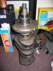
 Now that all the pistons are in place its time to lay in the crankshaft. Be sure to double check that the pistons are properly oriented, once the crank is in its difficult to re-orient the pistons.
Bearings
 With the engine inverted it should be easy to see where the bearings go. If you had to turn the crank or your crank has oddly sized journals be sure to place the bearing in the appropriate location. Many people like to use a plastigauge here to ensure everything has fit together properly and that no one has screwed up a measurement along the way. This is up to you. Different engines have different types of bearings, some have grooves, holes, are smooth. Some are directional some are not. The Fiat bearings have a little key that has to match up with the same on the block/cap/rod if you line these up you should be alright. Be sure to put some assembly lube on the bearing surfaces, this will prevent them from getting scuffed up during assembly.
Installation
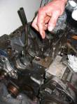
 Once the bearings are all in place its time to lay in the crank. Placing segments of rubber hose on the connecting rod bolts is a good idea and will keep you from accidentally marring the crank surface during install. The crankshaft is heavy so if you can get someone to help you that is a big plus. Once the crank is in place its time to torque down the main and rod caps. If you were planning on using a plastigauge now is the time to do it!
 Table of Contents